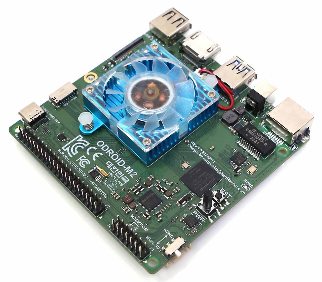
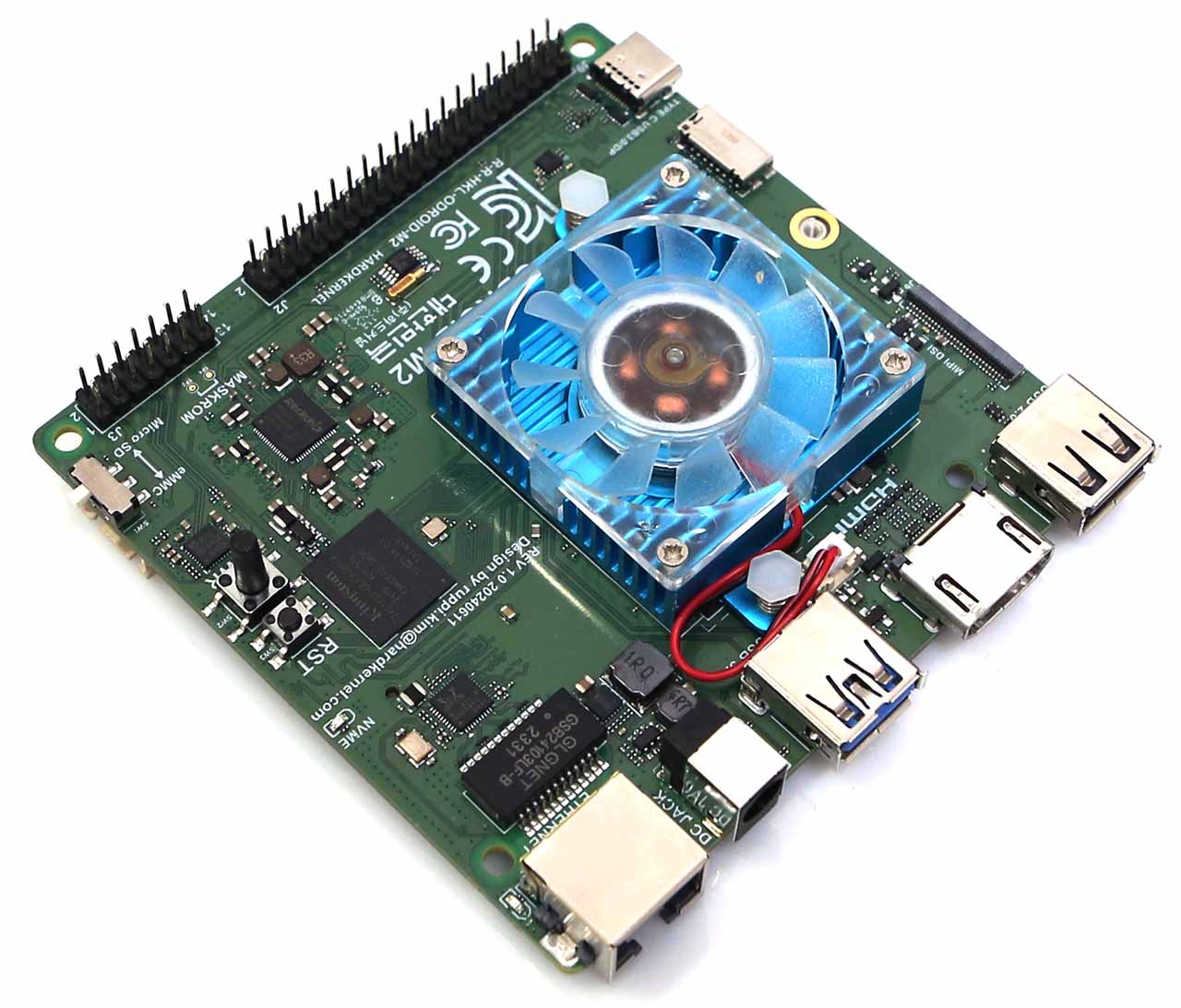
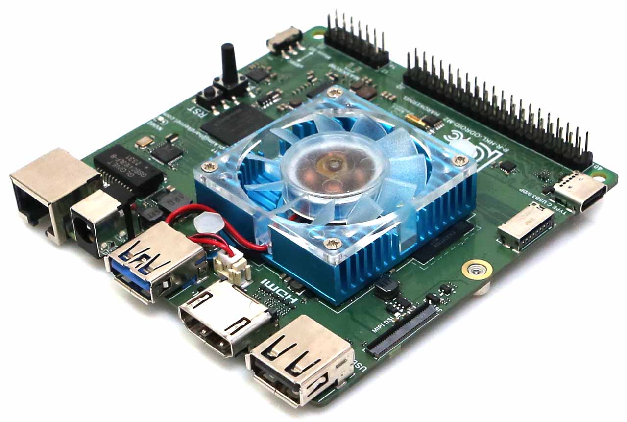
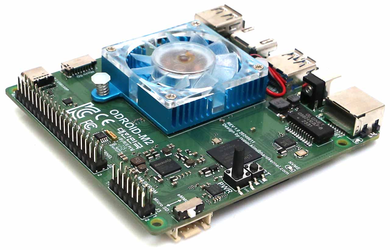
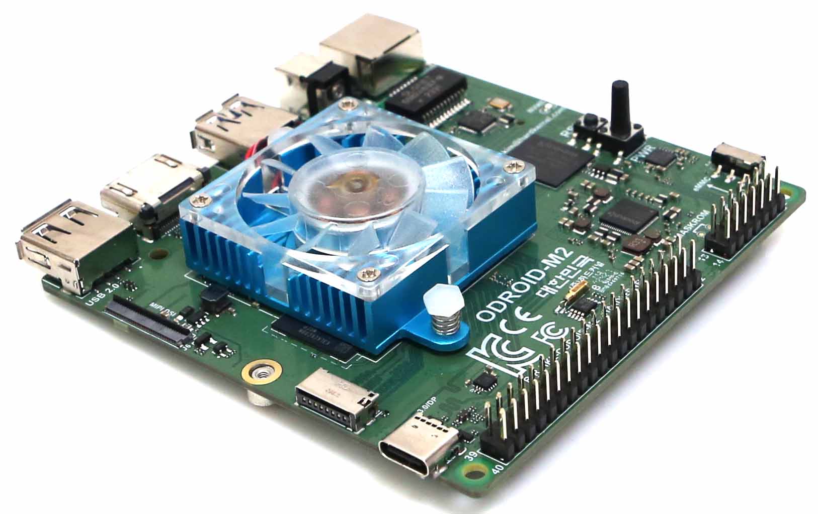
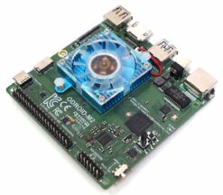
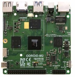
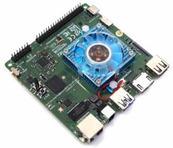
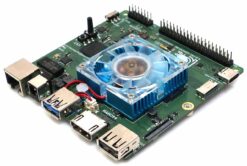
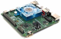
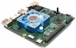
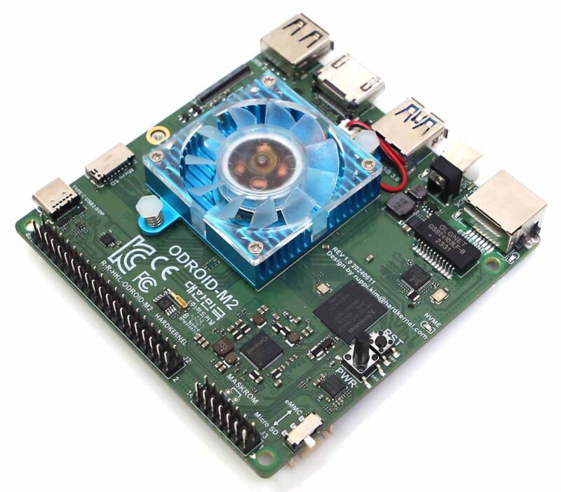
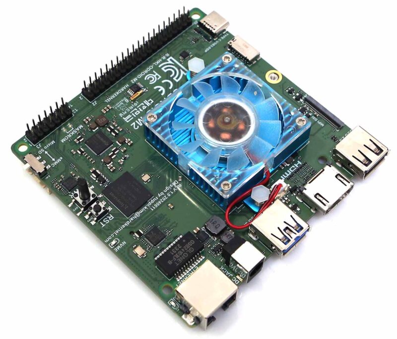
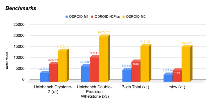
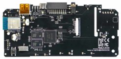
The M2 is a striking high performance SBC compared to the M1 series
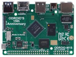
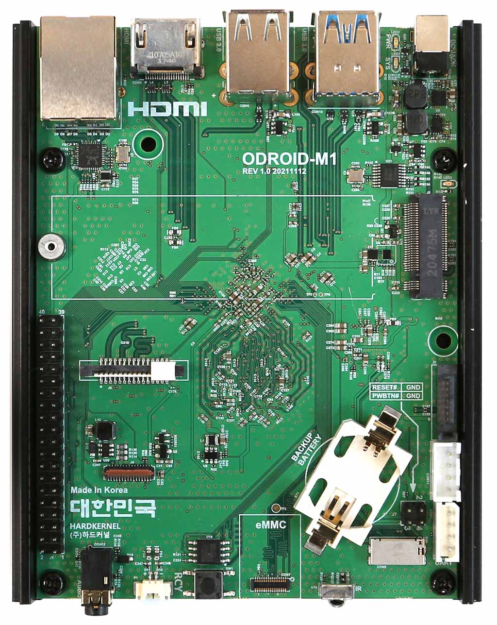
We launched the ODROID-M1 about 2 years ago, and the ODROID-M1S about 1 year ago. Both models have been successfully supplied and continue to be adopted as core components in embedded systems by our B2B customers.
We received feedback that the performance and input/output port configuration of the ODROID-M1/M1S were sufficient for most embedded systems. However some customers still wanted higher-end models equipped with high-performance processors. To meet the demand for higher performance computing power required by important industrial embedded system builders, we are launching the new ODROID-M2 SBC today.
Compared to the original ODROID-M1 (based on the RK3568B2 SoC), the ODROID-M2 uses the RK3588S2 SoC whose comparative characteristics are listed below:
- Multiprocessing performance is about 3 times faster.
- LPDDR5 64-bit RAM with a memory bandwidth that is more than twice higher.
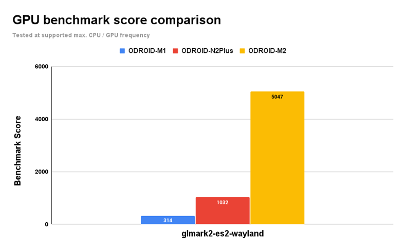
- A GPU that is more than 5 times faster.
- A NPU that is more than 3 times faster.
- An on-board 64GB eMMC storage device which is twice faster thanks to a HS400 interface.
The RK3588S2 SoC with multiple high-performance CPU/GPU cores and large cache memory blocks, is manufactured in the Samsung Foundry’s 8N process, and has the advantage of relatively low power consumption compared to performance.
Thanks to the high-speed 64-bit LPDDR5 memory and high-performance GPU, it shows very usable graphics performance in a 4K dual-head display configuration. We connected two 4K monitors using the M2 board’s HDMI port and the Alt-mode USB Type-C port. This demo shows 4K 3D rendering using HW GPU acceleration on the first monitor, and 4K video playback using HW VPU acceleration on the second monitor. Since hardware accelerators are used to run high-end graphics applications, the cooling fan rarely rotates because it does not generate a lot of heat.
4K Dual-head display demo video
Yocto with VPU accelerated Chromium browser
Yocto with GPU accelerated Chromium browser
Yocto Project How to Guide : https://wiki.odroid.com/common/board_support/open_embedded
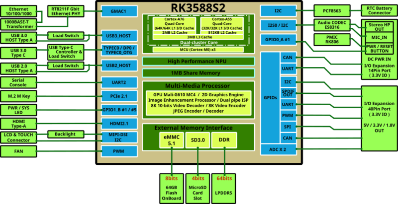
For detailed internal configuration, please refer to the block diagram shown below.
On-board eMMC storage
For the first time in the ODROID board series, an eMMC chip is soldered to the PCB by default instead of using a removable eMMC module. We think 64GB capacity is sufficient for building most embedded systems solutions of this category
The sequential access speed of the on-board eMMC is approximately 260MB/s, which is about 3 to 5 times faster than typical microSD cards. Note that the ODROID-M1 series supports the eMMC interface of the HS200 specification, but the ODROID-M2 supports the much faster HS400 specification.
|
Benchmark |
ODROID-M1 |
ODROID-M2 |
| iozone 1M random read | 144.29 MB/s | 273.25 MB/s |
| iozone 1M random write | 129.45 MB/s | 254.15 MB/s |
| iozone 4K random read | 27.52 MB/s | 27.86 MB/s |
| iozone 4K random write | 41.85 MB/s | 52.9 MB/s |
On-board M.2 NVMe slot
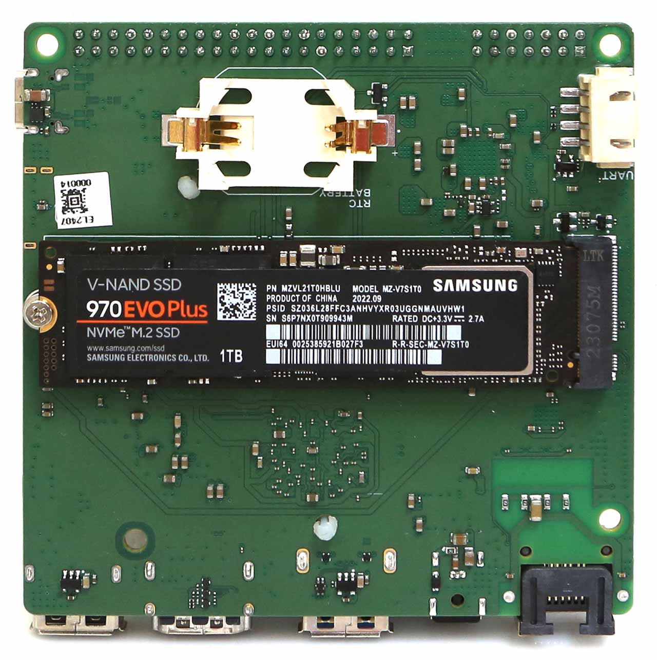
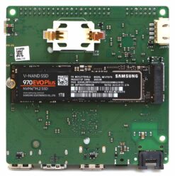
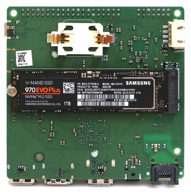
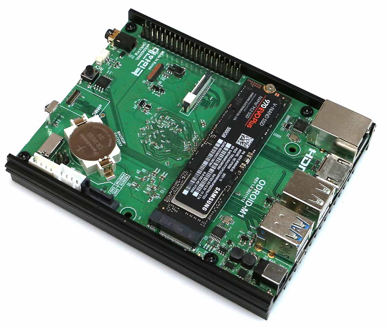
In case the 64GB storage space of the soldered eMMC memory is insufficient, consider using an industry standard M.2 2280 form factor NVMe SSD. An on-board M.2 NVMe slot is provided to access large amounts of data storage.
Unlike the original M1 model’s PCIe 3.0 x 2 lanes configuration, M2 has PCIe 2.1 x 1 lane. The NVMe transfer speed of the M2 has been reduced by about 1/4. However, we still believe that ~400 MiB/s of storage access speed is sufficient for building various high-end embedded systems. Note that M.2 SATA SSD storage devices cannot be used. The M.2 slot supports only the PCIe SSD (M-Key).
Real Time Clock
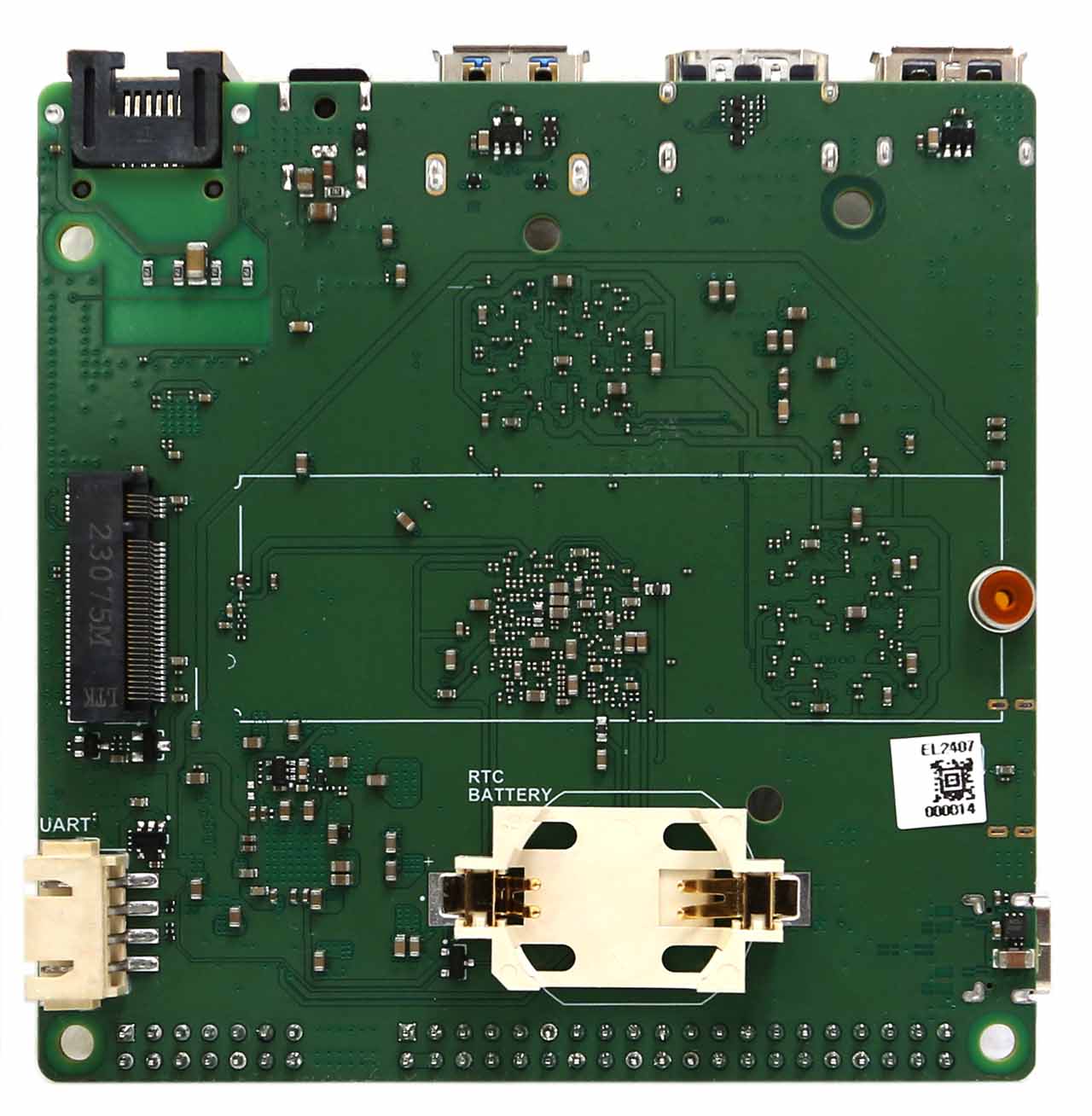
The ODROID-M2 has a hardware Real-Time Clock (RTC) and calendar function by embedding the low-power optimized PCF8563 chip. By installing just one CR2032 RTC backup battery, the clock and calendar will continue to operate for nearly 10 years without a main power supply. The battery is not supplied and must be purchased separately.
Heatsink cooling fan
A high-performance octa-core single-board computer requires power consumption close to 8 watts when the CPU and GPU are continuously subjected to high-computing loads. At this time, considerable heat is generated and a cooling fan is inevitably needed to avoid thermal throttling of the SoC. Accordingly, the cooling fan is included in the kit. The speed of the cooling fan can be controlled using PWM.
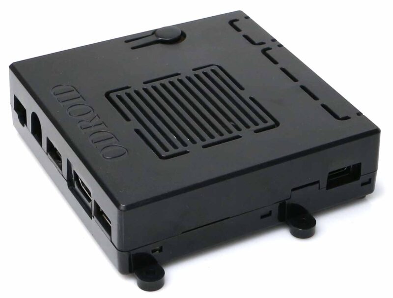
Free case
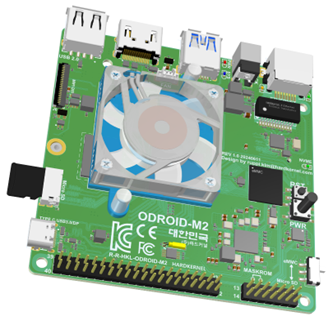
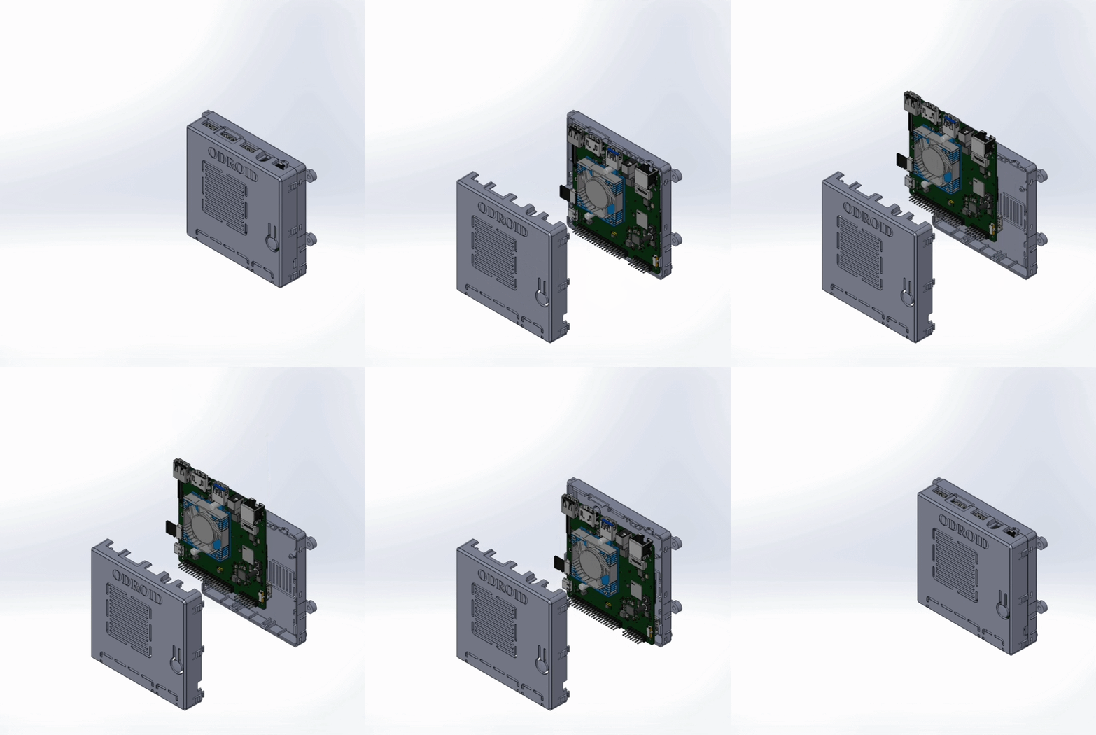
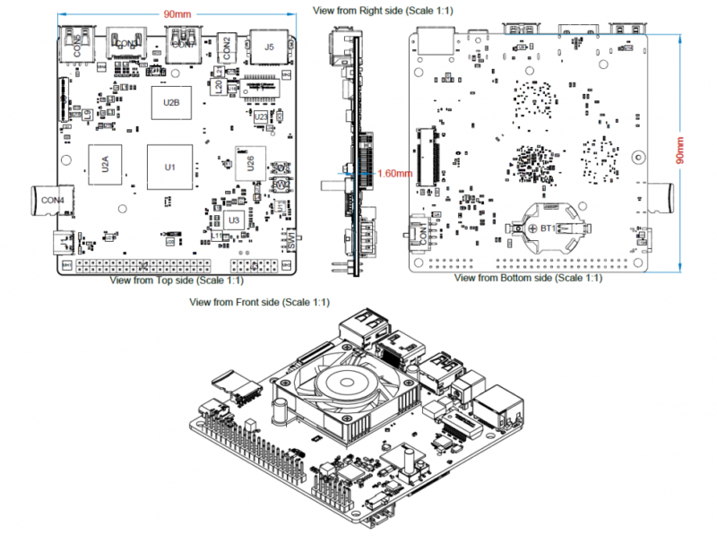
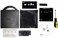
Using 3D modeling from the early PCB design stage, we were able to complete the case development precisely and rapidly. The case is also included in the kit.
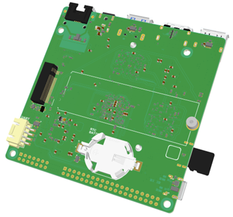
SBC 3D model and case
Power consumption
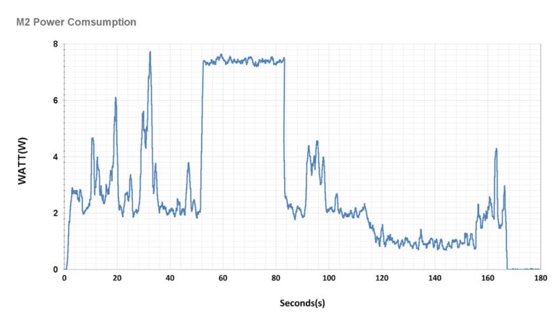
To create the graph below, we turned on the M2 and recorded the power consumption until the Ubuntu Desktop OS boots and enters Idle mode. We used the SmartPower3 device to examine power characteristics. See https://www.hardkernel.com/shop/smartpower-iii/.
With Ethernet and HDMI monitor connected, the peak power consumption is close to 8 Watts during booting and very heavy computing, but drops to 2 Watts in desktop GUI idle state.
If you remove the HDMI monitor for a headless system, power consumption in idle mode drops to near 1.3 Watt. Additionally, please note that when the Ethernet cable is unplugged, the power drops to 0.9 Watt.
Thermal characteristics
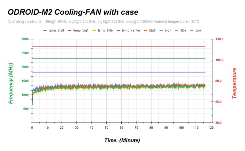
Thermal throttling does not occur even when performing a CPU stress test while mounted in a case. Because system power consumption is low, less heat is generated. Cooling is sufficient with just the stock heatsink fan.
As shown in the graph below, when a stress test was performed on ODROID-M2 with a stock heatsink under room temperature conditions of 35°C, the CPU temperature was about 75°C and maintained the maximum clock frequency. If the room temperature is 25°C and there is no case, the CPU temperature will be around 60°C.
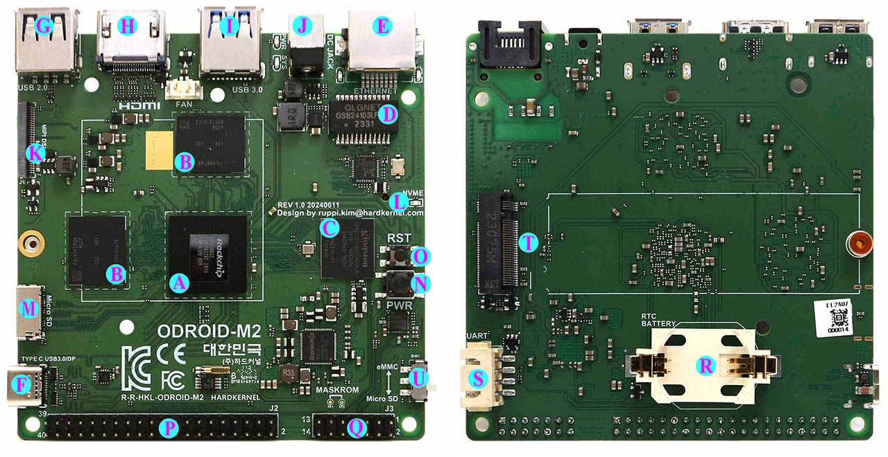
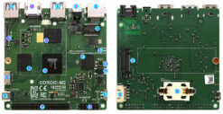
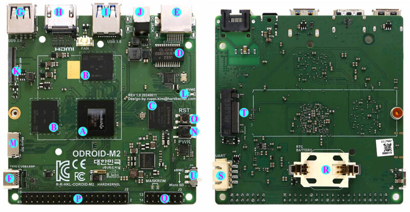
Board details
| A | Rockchip RK3588S2 CPU | K | 1 x MIPI DSI 4 Lanes |
| B | 2 x LPDDR5 chips | L | 1 x M.2 LED Indicator |
| C | 1 x 64GB eMMC on-board | M | 1 x Micro-SD Slot |
| D | 1 x Ethernet Transformer | N | 1 x Power Button |
| E | 1 x RJ45 Ethernet Port (10/100/1000) | O | 1 x Reset Button |
| F | 1 x USB 3.0 Type C with Alt-mod DP | P | 40 x GPIO Pins |
| G | 1 x USB 2.0 host | Q | 14 x GPIO Pins |
| H | 1 x HDMI | R | 1 x RTC backup battery holder |
| I | 1 x USB 3.0 host | S | 1 x UART for System Console |
| J | 1x DC Power Jack | T | 1 x M.2. M-KEY PCIe2.1 1 Lane |
| U | 1x Slide Switch (Boot mode select) |
Specifications
| Form Factor | Board Dimensions: 90mm x 90mm x 21mm Weight: 78g including heatsink, 58g without heatsink |
|---|---|
| Processor | Rockchip RK3588S2 Processor Quad-Core Cortex-A76 (2.3GHz +/- 0.1Ghz) Quad-Core Cortex-A55 (1.8GHz) ARMv8-A architecture with Neon and Crypto extensions Mali-G610 GPU MP4 (1Ghz)64KB L1 instruction cache, 64KB L1 data cache, 512KB L2 cache, shared by Cortex-A76 processor 32KB L1 instruction cache, 32KB L1 data cache, 128KB L2 cache, shared by Cortex-A55 processor L3 data cache: 3MB, shared by 8 processors |
| NPU | 6 TOPS@INT8, Integrated AI accelerator RKNN NPU |
| Memory | LPDDR5 8 or 16GiB with 64-bit bus width |
| Storage | 1 x 64GB eMMC embedded (soldered to the PCB) 1 x Micro SD slot (UHS-I SDR104) * Boot priority between eMMC and microSD can be selected with the slide switch 1 x NVME M.2 SSD (PCIe 2.1 x 1 lane) |
| Networking | 1 x GbE port (RJ45, supports 10/100/1000 Mbps) – LED indicators * Green LED: Flashing by data traffics at 100Mbps connection * Amber LED: Flashing by data traffics at 1000Mbps connection |
| Video output | 1 x HDMI 2.0 (up to 4K@60Hz with HDR, EDID) 1 x MIPI DSI Interface (30pin connector which is different from 31pin of the ODROID-M1) 1 x DP (via USB Type-C port) |
| External I/O | 1 x USB 2.0 host port 1 x USB 3.0 host port 1 x USB 3.0 Type-C (Data communication and DP Alt-Mode, Not a power source/sink) 1 x Debug serial console (UART) 1 x 40 pin GPIO and 1 x 14 pin GPIO |
| Real Time Clock | * On-board very low power PCF8536 RTC chip * CR2032 RTC backup battery holder to keep time and date for near 10 years without main power input |
| Other features | * Power button * Reset button * System LED Indicators: – Red (POWER) – Solid light when DC power is connected – Blue (ALIVE) – Flashing like heartbeat while Kernel is running. Solid On in the u-boot stage. |
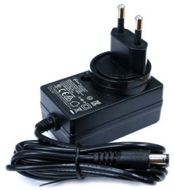
| Power | 1 x DC jack: outer (negative) diameter 5.5mm inner (positive) diameter 2.1mm DC input voltage range: 7.5V ~ 15.5V (12V/2A power adapter is recommended) – IDLE : ≃ 1W without any kind of peripherals – CPU Stress : ≃ 7.5W (Performance governor) without any kind of peripherals – Power Off : ≃ 0W |
Note: The maximum clock speed of the Cortex A76 big cores is between 2.2GHz and 2.4GHz. (2.3GHz +/- 0.1GHz)
In the semiconductor factory’s test process, the power, voltage and thermal characteristics of each individual CPU are measured and the appropriate maximum clock value is stored in OTP memory as a PVTM. This value cannot be changed by the user.
When we tested over 100 samples of M2 boards, most were in the 2.2 ~ 2.3 GHz range, while only a few exceeded 2.3 GHz.
GPIO Header
There are 40-pin and 14-pin header pin connectors for general purpose input and output functions.
Digital IOs, UARTs, I2Cs, PWMs, ADCs, SPI, Analog audio output, Power-on and Reset signals are available.
IMPORTANT: Please note that the ODROID-M2 14-pin header pin-map is quite different from the ODROID-M1S due to the missing USB 2.0 signals and different power rails.
MIPI-DSI
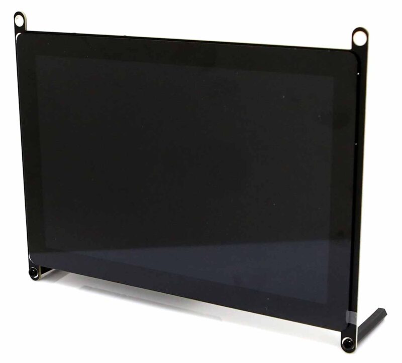
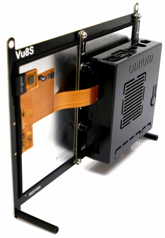
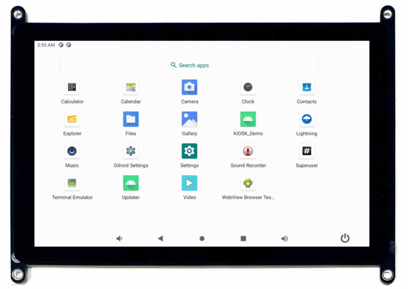
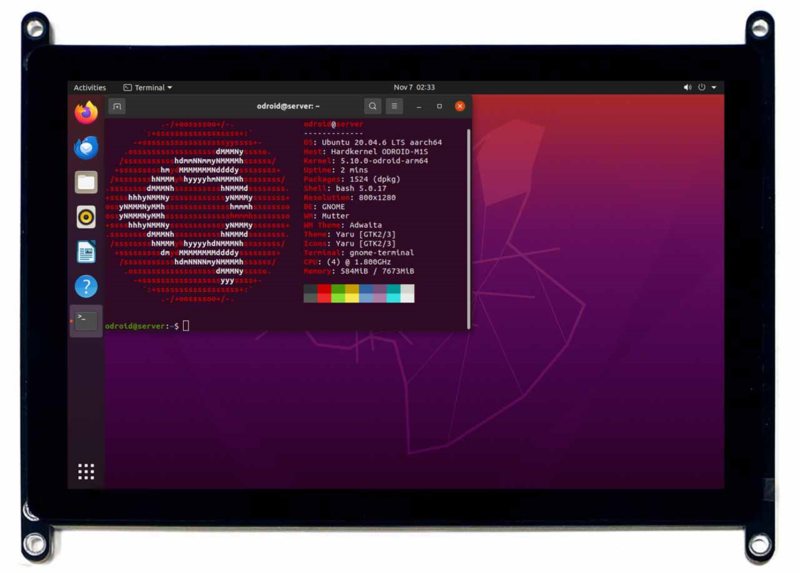
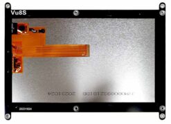
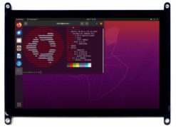
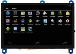
The four-lane MIPI-DSI port can be directly connected to an LCD panel. The ODROID-Vu8S kit with an 8 inch, 800×1280 wide viewing angle LCD and capacitive multi-touch screen is an available option. See https://www.hardkernel.com/shop/vu8s-8inch-mipi-lcd-for-m1s/.
If you assemble the ODROID-M2 single board computer on the rear side of the Vu8S kit, you can easily implement a Human-Machine-Interface (HMI) device with Android as well as Linux.
Software support
- Android 13
- Based on AOSP Tiramisu
- Customized raw GPIO access framework : Android Things with various examples (https://wiki.odroid.com/common/android_things)
- I2C (Color sensor, Temperature, Humidity, OLED, RTC)
- SPI ( CAN receiver, LED strip lights, IO expander)
- UART ( Loopback test, Barcode scanner, Thermal printer)
- GPIO toggling
- Rotary encoder with GPIO IRQ
- PWM outputs
- Ubuntu 20.04 LTS (24.04 with newer kernel version will be available a few months later)
- Kernel 5.10
- Wayland based GNOME desktop
- ARM Mali Bifrost GPU OpenGL-ES / EGL driver
- MIPI DSI driver
- GPIO drivers and WiringPi library
- NPU driver and Neural Network APIs
- VPU driver with MPP/Gstreamer APIs
WIKI : https://wiki.odroid.com/odroid-m2/odroid-m2
GTIN : 8809543642775
- The terms HDMI, HDMI High-Definition Multimedia Interface, HDMI Trade dress and the HDMI Logos are trademarks or registered trademarks of HDMI Licensing Administrator, Inc.
- HDMI, HDMI High-Definition Multimedia Interface(고화질 멀티미디어 인터페이스), HDMI 트레이드 드레스 및 HDMI 로고라는 용어는 HDMI Licensing Administrator, Inc.의 상표 또는 등록 상표입니다.

 English