-
×
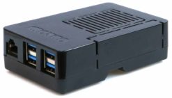
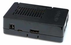
 H4 Cube Case
1 × $25.00
 -
×
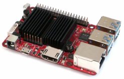
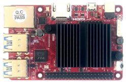
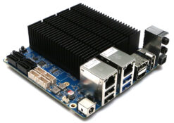 ODROID-H4 ULTRA
1 × $220.00
 -
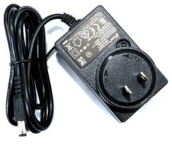
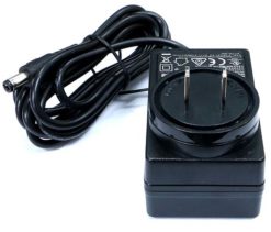
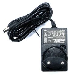
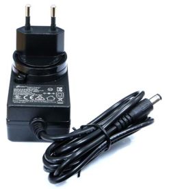
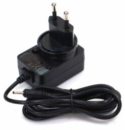
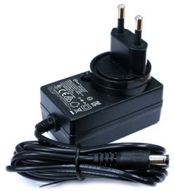
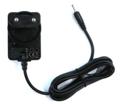
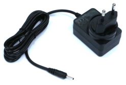
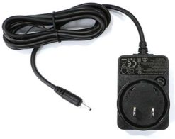
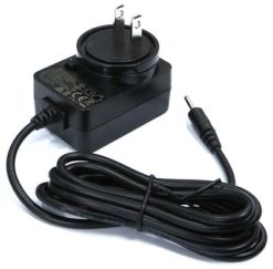
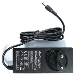 15V/4A power supply EU plug
1 × $9.40
C Tinkering Kit
$16.00
SKU: G141637532784
Category: Development
Tags: ODROID-C0, ODROID-C1+, ODROID-C2, ODROID-C4, ODROID-M1, ODROID-M1S
for ODROID-C2 / ODROID-C1+ / ODROID-C4
You’re probably itching to make some fun embedded computer projects with ODROIDs. What you need is an add on prototyping T-breakout board, which can break out all those tasty power, GPIO, I2C, ADC pins from the 40 pin header onto a solderless breadboard. This set will make “cobbling together” prototypes with the ODROID super easy.
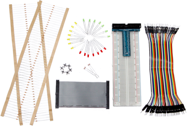
This kit comes with below many items.
– Assembled T-breakout PCB – 40Pin GPIO Breakout board
– Breadboard – 630 Tie-points with dual power lanes
– 40pin Ribbon cable – IDC Flat cable 100mm
– 40pin Male-to-Male Dupont jumper Wire 170mm
– 7 x Green LED 3mm
– 7 x Yellow LED 3mm
– 7 x Red LED 3mm
– 2 x Photo Cell (CdS Light sensor)
– 6 x Tact Swithc
– 50 x 330 Ohm 1/6W resister
– 50 x 10K Ohm 1/6W resister
WiKi : https://wiki.odroid.com/accessory/development/c_tinkering/c_tinkering
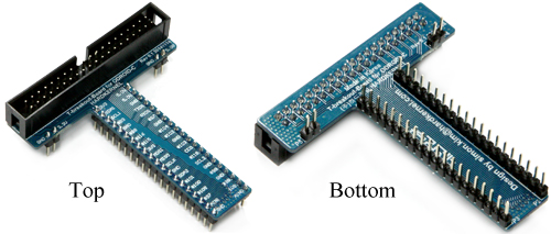 With this T-type breakout board you can easily break out the GPIO pins of the ODROID-C1 on a breadboard to quickly start prototyping. The ribbon cable comes at the side of the breadboard so it won’t be in the way while working on your project. This breakout also has the possibility to provide +5V and +3.3V to the power rails on a 630 points breadboard.
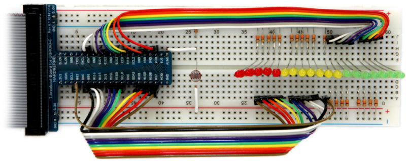
Simple project with the C1 Tinkering Kit.
19 LEDs + CdS light sensor will show you how ADC and LED work.
Notes: The CdS is connected to the ADC #0 port with a 10Kohm ground bias. 3.3V – CdS – Cds – ADC – GND. The LED is connected to the GPIO via 330ohm in serial. GPIO – LED(A+) – LED(K-) – 330ohm – GND
Connect it to your ODROID-C1 with the Flat cable.
The example code and library can be found in our WiKi and Github repo.
GTIN : 8809543643314
Related products
Sale!
Cables
Sale!
Dollar Shop
Sale!
Dollar Shop
Sale!
Power Supply & Battery
Sale!
Dollar Shop
Sale!
Dollar Shop
Sale!
Dollar Shop

 한국어
한국어
