(DISCONTINUED)ODROID-VU5 : 800×480 HDMI multi-touch display
$0.00
OBSOLETED
This product is no longer available.
Out of stock
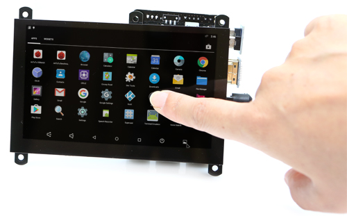
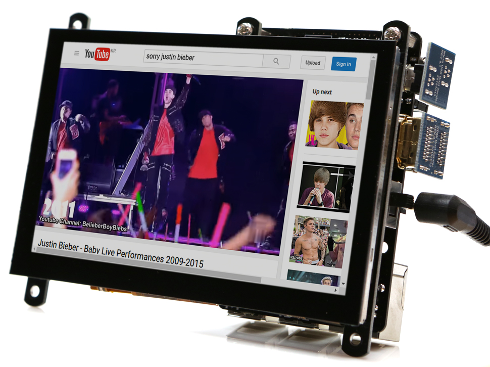
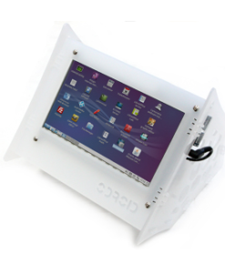
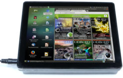
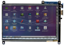
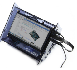
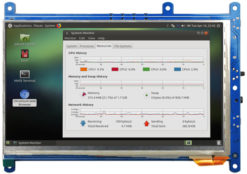
ODROID-VU5 : 5inch 800×480 HDMI display with Multi-touch
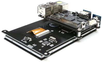
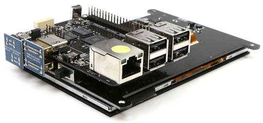
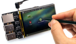
5-inch multi-touch screen for ODROIDs gives users the ability to create all-in-one, integrated projects such as tablets, game consoles, infotainment systems and embedded systems. The 800×480 display connects to ODROID-C2 / C1+ via an HDMI link board and a micro-USB link board which handles power and signal. Just connect a DC plug in to the DC-jack on C2 / C1+, and you are ready to play, once you install the latest OS up- date. This high-quality touchscreen is specifically designed to work with both Android and Linux on the ODROID-C1+, ODROID-C2 and ODROID-XU4.
Specifications
– 5-inch TFT-LCD
– Screen Resolution: 800×480 pixels
– 5 finger capacitive touch input (USB ID 16B4:0704)
– Power consumption : 500mA/5Volt
– Backlight on/off slide switch
– Viewing angle (in degree) : Left 70, Right 70, Up 70, Down 50
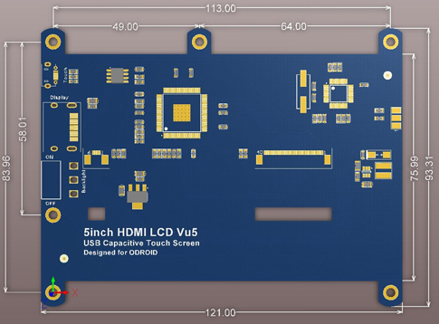
– Screen Dimensions : 121 x 93.31 x 15 mm Including switch and connectors)
– Viewable screen size : 108 x 64 mm (active area)
WiKi : https://wiki.odroid.com/accessory/display/vu_series/vu5/vu5
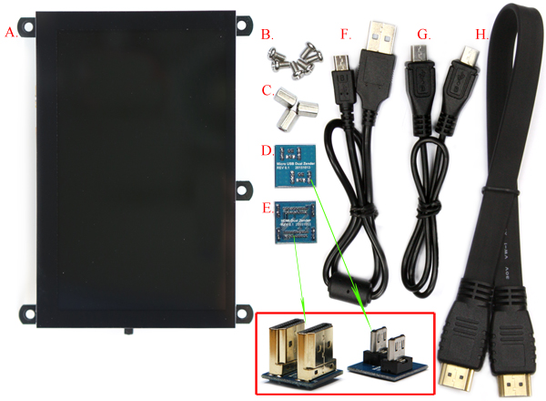
Package include
A. Fully assembled 5inch TFT LCD + 5 point multi touch screen
B. 6 x 3.5mm screws
C. 3 x Hex nuts
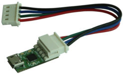
D. Micro USB link board
E. HDMI link board
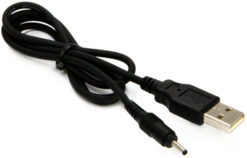
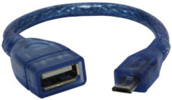
F. Micro-to-TypeA USB Cable (approx. 35cm)
G. Micro-to-Micro USB Cable (approx. 35cm)
H. TypeA-to-TypeA HDMI cable (approx. 35cm)
Assembly Guide
You can easily attach the C2 / C1+ board onto the backside of the LCD screen in order to create a fully integrated system. It also works with the original C1 board if you use a micro-HDMI cable and a micro-USB cable.
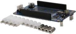
Option 1 : Mount the C1+ board on the LCD unit with 3pcs of 8mm PCB supporters. The HDMI link board and micro-USB link board are used for interface and power supply.
Option 2 : A Micro-to-micro USB cable and flexible flat HDMI cable can be used as well. The 35cm cable kit is included.
with ODROID-XU4
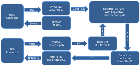
Block Diagram Physical Dimensions
Make a standalone multimedia system
Known issues.
1. The display shows noise on the screen in the boot process and power-down process because there is no off-sync filter circuit.
2. On the C1+, there will be after-image or noise when the system turns off if you use the OTG port.
To fix this issue, you must remove(de-solder) the R94 from the C1+ PCB.
If you have the C1+ PCB Rev 0.4 2015/09/30, just remove a JUMPER on J8.
3. There is no backlight control except for the slide switch. So software can’t adjust the brightness neither turn on-off the backlight.
Related products
Obsolete Products
Obsolete Products
Obsolete Products
Obsolete Products
Obsolete Products
Obsolete Products
Obsolete Products
Obsolete Products
Obsolete Products
Obsolete Products
Obsolete Products
Obsolete Products
Obsolete Products
(DISCONTINUED)ODROID-VU7A Plus: 7inch HDMI display with Multi-touch and Audio capability
Obsolete Products
Obsolete Products

 한국어
한국어
